Top Page 1 Page 2 Page 3 Page 4 Page 5 Page 6 Page 7 Page 8
Phew, the soldering iron is fine. I give it a bit of solder to tin it, wipe it down on the moist sponge, and get back to my wire identification problem.
OK, no problem. I've got a multimeter, right? I can use it, right? It's no big deal to check a few wires, right? After all, I just need to locate a switched 12 volt source.
Where in the hell was my multimeter?
Let's fast-forward here: Searching, yelling, throwing, unplugging soldering iron, screaming, ranting, finding in a kitchen drawer for some reason?!?
Calm down, take it easy... Let's install the electrics.
I'm a software developer by trade, and I believe in constant testing as I go. I don't see why I should do things any differently here. At each step, I verified that things were working, mostly just to reassure myself that I hadn't gone astray somewhere.
Now, we get to testing the leads. We need to find a switched power supply, and this is how I did it.
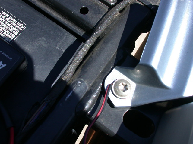
The pointed ends on the multimeter probes make this a very straightforward job. You put the black point against a known good ground, and you push the red point through the wire's insulation to make contact with the conductor inside. In my case, I used a screw that goes into the subframe as a ground (I tested it by going right to the battery with the red probe). Don't forget to put the ignition on, or there won't be any power to the tail light.
Subframe screw I used for grounding:
You'll know that you've gotten a good contact when your multimeter (Set to measure Volts DC, or 'VDC' on mine) changes from near-zero to read somewhere around 12 volts. The thing will change from this:
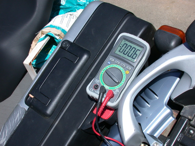
To something much more like this:
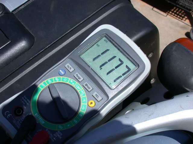
Then as an extra sanity check, I cycled the ignition a couple of times while maintaining the test probe's contacts. That's a bit tough without an assistant, but it's nice to see the power cycle on and off with the ignition. For the record, it's the gray and black wire on my 2001 model year bike.
Now I was ready to tear into the wiring. I clipped a couple of zip ties and removed more of the tape from the wiring harness. Then I stripped the insulation from about 3/4" of the gray/black wire. I wrapped the bare end of the red Autocom (Positive) wire around the exposed wire, and trapped the bare end of the black Autocom (negative/ground) wire under the same chassis screw I used before. I also chose to use this screw for my Autocom ground point, despite the manual's recommendation to go all the way to the battery. I figure shorter wires are better, and the subframe isn't going to lose the ground connection any time soon.
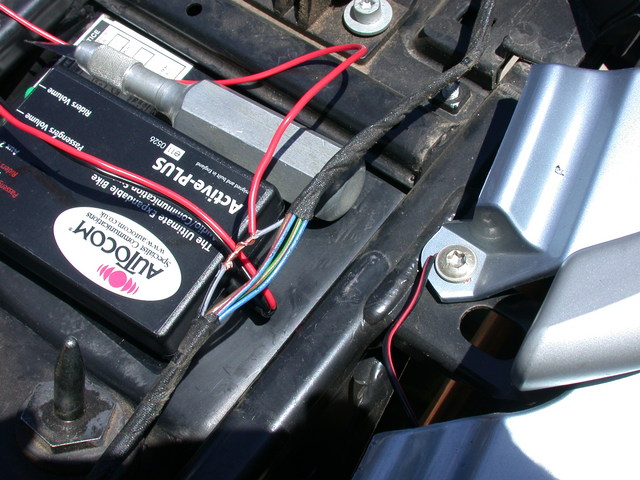
With this temporary setup I was finally able to test the Autocom running on bike power. I put on my helmet, and plugged it in to the bike.
Turned on the ignition switch... And I could hear myself speaking in the helmet speakers!
It Verks!

Alright! That's real progress. Now we can get things permanently installed to the bike, with some level of confidence...
OK, enough beefcake. Let's get back to finishing up the install.