Top Page 1 Page 2 Page 3 Page 4 Page 5 Page 6 Page 7 Page 8
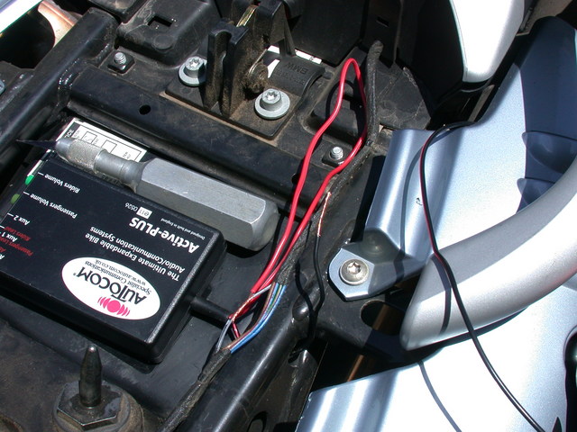
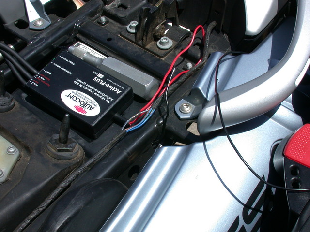
The Autocom comes with power wires that are several feet long. Since I was installing it so close to my power supply, I had to cut 'em. However, I did leave a bit of extra wire attached (you'll see the extra red power wire folded back along the bike in some pictures). This is so I can pull out the Autocom for maintenance, or in case of a boneheaded mistake I had some options. The black wire is routed under the subframe rail through a convenient hole.
Snip, snip, and the job was done. I stripped a bit of insulation off of the new ends and tightly twisted the black (ground) one. I wrapped the exposed red wire around the exposed black/gray taillight wire. Then I tinned the black wire and soldered the red wire into place. It's a bit hard to see the difference between these two pictures, but in this second one the exposed wires have a silvery tint to them from the solder. If you don't know what tinning is, it's just pre-soldering a component before attaching it to anything.
I was feeling good now. I crimped and soldered the provided ground connector on to my tinned ground wire, and wrapped the wiring harness back up with the provided rubbery tape.
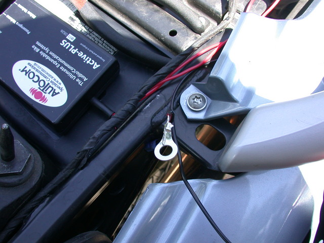
At this point I was nearly finished. I removed the chassis screw and trapped the ground ring with it.
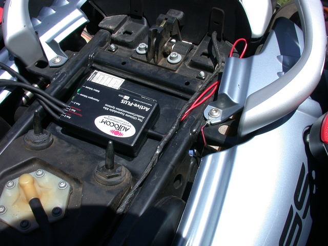
I ran another helmet test, cycling the ignition and hearing the unit powering up and down. I won't insult you with more pictures of me, but I was happy as a clam. I replaced the zip ties I had cut, and I was essentially done, with the exception of some tidying up work.